

Welcome to the Basics of Electrical / Electronic
Theory and Components

In this course, we’ll explore electrical theory and components, and how electrical and electronic devices help us harness and control electrical energy. By tapping into the fundamental behavior of atoms, electrical and electronic components enable everything from illuminating our homes to powering cutting-edge artificial intelligence.
In the coming lessons, you’ll learn about the key components that make up electrical circuits, and how they work together to utilize, and control the movement of electrons. Understanding how these components function and interact is essential for understanding, designing, troubleshooting, and improving electrical systems.
Whether you're looking to build simple circuits, repair devices, or pursue a career in electrical engineering, this course will help to equip you with the foundational knowledge to get started. By the end of this course, you’ll have a strong grasp of basic electrical theory of the most common components, their purposes, their composition, how they function, and how they work together to form fully operational circuits.
Electrical and Electronic Components: What's the Key Difference?
Clarifying Electrical vs. Electronic Components:
While the terms "electrical components" and "electronic components" are often used interchangeably, they are not entirely synonymous. The distinction lies in their functions, applications, and the types of systems in which they are used.
-
Electrical components focus on power handling and distribution (dealing with higher currents and voltages).
-
Electronic components are generally low power devices, focus on signal processing, amplification, or switching in low-power systems (managing small currents and voltages to process information or control logic).
-
While there is overlap (components like resistors, capacitors, coils, and diodes are used in both electrical and electronic systems), the primary difference lies in the purpose and application of the components—whether they are used to handle or manipulate electrical energy or signals.
Electrical Components:
Electrical components focus primarily on power handling, such as distributing, controlling, or protecting electrical energy in circuits with high current and voltage. These components are integral to systems that manage power, such as electrical grids, large machinery, and household appliances. They deal directly with the movement and regulation of electrical energy in the form of high voltages and currents.
Common electrical components include:
-
Resistors: Control the flow of current
-
Capacitors: Store and release energy for power regulation
-
Fuses: Protect circuits by breaking the connection in case of overcurrent
-
Transformers: Change voltage levels
These components are used in power systems where the primary concern is the flow and distribution of electrical energy.
Electronic Components:
Electronic components, on the other hand, are typically used for signal processing, switching, or amplification in circuits that deal with low current and voltage. These components are central to systems like computers, radios, and communication devices, where their function is to process information or control logic. These components' main role is to manipulate electrical signals, such as in amplification or switching, rather than simply managing or distributing power.
Common electronic components include:
-
Transistors: Amplify signals or switch electronic signals on/off
-
Diodes: Allow current to flow in one direction only
-
Integrated Circuits (ICs): A package of multiple electronic components that perform complex functions
-
Microprocessors: Perform computations and manage logic in devices
These components are found in signal-processing systems where the goal is to control or manipulate information rather than just distribute power.
Physics the Key of Understanding Electrical & Electronic Components

The relationship between physics and electrical engineering is foundational and inseparable. Electrical engineering, as a field, is built upon the laws of physics. Without physics, there would be no way to develop the technologies we rely on today, like LED lighting, electric motors, and complex computer circuits—because the underlying principles of how electricity behaves and how it can be manipulated are rooted in material engineering, and physics. It's this understanding that allows engineers to design, control, and innovate electrical systems.
From the simple circuit to the complex interactions in modern microprocessors, physics explains how and why electrical components work the way they do. Without physics, electrical engineering wouldn't have the tools or principles to create anything beyond basic experimentation.
It is through physics that we can transform the invisible power of electrons into usable energy, energy that powers everything from LEDs to AI. Without physics, there would be, no batteries, no AC power, no electrical systems of any kind. Electrical engineering, in fact, would not exist without the principles of physics to guide it. Physics is the very essence of how we explain, design, and control electrical devices.
An in-depth knowledge of electrical components relies on an appreciation of physics as the essential underlying science. The relationship between physics and electrical engineering is foundational and inseparable.
Therefore, understanding basic physics concepts is absolutely essential for anyone wishing to understand electric and electronic components, in depth, or pursuing electrical engineering. It is the starting point for understanding how electrical devices work, and it is the cornerstone upon which we build the ability to harness and manipulate the atoms of materials and substances for practical use. Without this knowledge, there would be no way to unlock the potential of the technologies we depend on every day.
Defining Electricity

Electricity is a natural phenomenon and a form of energy created by the movement of charged particles, mainly electrons, through a material. This flow can occur in solids, liquids, gases, or even vacuums, and is not limited to any specific material or environment.
The term "electricity" refers to the movement of charged particles and the intricate interactions between electrons in different atoms. These interactions are not directly visible to us because subatomic particles, like electrons, are extremely small and move at such high speeds that they are invisible to the naked eye.
At the heart of all matter is the atom, the fundamental unit of everything. An atom consists of a nucleus made up of protons and neutrons, with electrons orbiting around it. Electricity occurs when electrons move from one atom to another. This can happen naturally or be driven by an external energy source, like an electrochemical battery.
When electrons flow through a material, it creates an electric current. Understanding how these electrons move is crucial to understanding the operation of electrical components like switches, resistors, capacitors, and transistors in a circuit. Without this knowledge, we wouldn’t be able to design or use components that control, store, or transfer energy in modern electronics.
Although the term "electricity" is widely used in industries like utilities, it has less relevance in electronics. Electrical engineers and professionals in the field focus on more precise terms like voltage, current, resistance, and power—concepts that provide a clear understanding of how electrical circuits and components behave.
The Concept of Electricity:
A Model Based on Observation and Mathematics
To understand and control electricity, humans have developed models and concepts based on observation, testing, and mathematics. These models allow us to predict, measure, and harness the flow of electrons for countless applications.
The study of electricity began with observation and experimentation, leading to the development of mathematical laws that describe its behavior. Early pioneers like Benjamin Franklin conducted experiments showing that electricity could be stored and transferred. Thomas Edison further advanced these discoveries, bringing electricity into homes and businesses, and laying the foundation for modern electrical systems.
These experiments led to the development of mathematical formulas that not only describe how electricity behaves, but also gave engineers the tools to create electrical components and circuits. For example:
-
Ohm’s Law (V = I × R), developed by Georg Simon Ohm, describes the relationship between voltage, current, and resistance in a circuit. This law helped engineers design resistors that control the flow of electrical current by providing resistance, enabling devices to function efficiently.
-
Faraday’s Law of Induction, discovered by Michael Faraday, demonstrated how a changing magnetic field could generate an electric current. This law led to the development of electric generators, transformers, and other components crucial for modern power systems.
-
Maxwell’s Equations refined our understanding of electromagnetism and led to the development of capacitors, inductors, and diodes. These components store and transfer electrical energy, smooth out voltage fluctuations, and filter signals in modern electronics.
In the 20th century, advancements in semiconductor physics revolutionized electronics. The development of transistors and integrated circuits (ICs) enabled the creation of smaller, faster, and more efficient electronic devices. Mathematical models governing semiconductors made it possible to design components that regulate the flow of electricity with precision.
Mathematics and Modern Electronics
Mathematical formulas and principles, born from observation and experimentation, are not just theoretical. They provide the blueprint for the engineering of modern electronic components, such as resistors, capacitors, transistors, and transformers. These components are the building blocks of everything from smartphones to advanced computing systems.
Math, You Need to Know for Electrical and Electronics Jobs
Whether you're installing wiring as an electrician, troubleshooting systems as a technician, or designing large-scale power networks as an electrical engineer, mathematics is a foundational tool. It provides the structure, accuracy, and predictability needed to design, manufacture, and install modern electrical systems safely.
Different Roles, Different Mathematical Demands:
Electricians bring a strong foundation of mathematics, practical experience, and code knowledge to their work. They regularly apply arithmetic, algebra, ratios, fractions, and unit conversions to perform essential tasks such as calculating voltage drop, determining conductor sizes, and ensuring proper circuit loading. A thorough understanding of Ohm’s Law, power formulas (P = V × I), and other electrical principles is fundamental, not only for system functionality but also for safety and compliance.
Beyond math, electricians must have a deep familiarity with the National Electrical Code (NEC) or other regional codes, and the ability to interpret blueprints, schematics, and installation specifications. Their work involves a mix of technical knowledge and physical installation, often working in dynamic or challenging environments. Whether wiring a home, troubleshooting a commercial system, or maintaining industrial power infrastructure, electricians play a vital role in keeping electrical systems safe, efficient, and reliable.
Electrical Technicians often have strong foundations in algebra, trigonometry, and advanced topics such as Boolean algebra, calculus, and even differential equations, depending on their training and specialization. In addition to interpreting electrical schematics, a core part of their skill set, many technicians are also capable of designing circuits, performing in-depth circuit analysis, and applying engineering-level problem-solving in practical contexts. Their troubleshooting abilities are grounded in a deep understanding of how voltage, current, and resistance interact in real-world systems, often involving multi-step calculations, diagnostic logic, and critical thinking.
Electrical Engineers Electrical Engineers are typically responsible for the theoretical design, modeling, and optimization of electrical systems at every scale, from microelectronics to power grids. Their work requires fluency in advanced mathematics, including linear algebra, calculus, complex numbers, Laplace transforms, and differential equations. These tools allow engineers to predict behavior, analyze performance, and develop new technologies long before they are built. Engineers must also consider efficiency, safety, cost, and long-term reliability, often balancing multiple variables through simulation and modeling. This high-level problem-solving and system design capability is why engineers occupy top-tier roles in the electrical and electronics industry.
A Brief History – The Origins of Electronic Components


Benjamin Franklin
The history of electricity and its application to technology is a story of curiosity, experimentation, and breakthrough discoveries. It all began with early pioneers like Benjamin Franklin, whose fascination with the forces of nature and electrical phenomena set the stage for more systematic scientific inquiry. Franklin’s experiments in the mid-1700s—such as his famous kite experiment—were crucial in sparking widespread interest in electricity.
He observed and documented key behaviors of electrical charge, such as the attraction and repulsion between objects and the concept of "positive" and "negative" charges. Though Franklin's experiments helped to lay the groundwork for future discoveries, they were limited. His work with static electricity, while important, was confined to irregular, non-reproducible phenomena, and lacked the necessary foundation for further experimentation: a reliable power source.
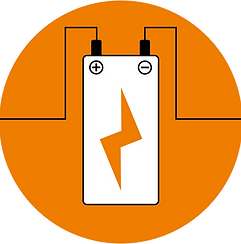

Electrical Symbol for Battery

+
_
Everything changed in 1800, when Alessandro Volta, an Italian physicist, created the first chemical battery, known as the Voltaic Pile. It was the first device capable of continuously producing electricity through a chemical reaction. Volta’s invention of the Voltaic Pile, the first chemical battery, marked a true turning point in the history of electricity.
The battery provided the first steady, controllable source of electrical current, making it possible to conduct systematic, repeatable experiments. For the first time, scientists could generate and control electrical current with reliability and consistence- something that had been impossible with earlier methods, which relied on static electricity or unpredictable natural phenomena like lightning. Volta's invention was not just a breakthrough in providing a power source; it unlocked a floodgate of scientific progress. The ability to generate a constant flow of current led directly to the development of key electrical components and technologies, and without it, nothing would have been possible.
The electromagnet, for instance, emerged from experiments with the battery. By passing an electric current through a wire coiled around a metal core, scientists discovered that a magnetic field could be created. This principle would later become foundational for the development of motors and electrical machinery.
While a battery is generally considered a power source rather than a traditional electrical component, it, along with copper wire, can be seen as the first essential components in the discovery and understanding of electricity. These foundational tools played a crucial role in the development of modern electrical components and systems.
The invention of the battery was monumental because, before Alessandro Volta's creation of the battery, there was no practical way to experiment with electricity. You can't study or understand something unless you have the means to explore it. In other words, without the ability to generate and electrical power, experiments on electricity were simply not possible.


In the early 1800s, Samuel Morse took advantage of this new understanding of electricity to invent the telegraph, which became one of the first practical applications of electrical power. The telegraph used the battery to send electrical signals over long distances, enabling instantaneous communication—a major leap forward for humanity. Morse’s telegraph, powered by the battery, revolutionized communication, allowing messages to be sent across continents in a matter of minutes.
However, the telegraph was just the beginning. The light bulb, often associated with Thomas Edison, was the next major leap. Edison’s work, beginning in the late 1800s, was made possible by the steady, reliable power provided by the battery and early electrical distribution systems. Edison didn’t just invent the light bulb; he created an entire electrical infrastructure, including generators and power grids, to make electrical lighting feasible for widespread use. His incandescent light bulb transformed daily life, providing the world with a reliable, safe, and practical source of light powered by electricity.
But the battery and direct current (DC) systems were not without limitations. Long-distance transmission of electricity was inefficient, and this created a challenge for the growing demand for electrical power. Enter Nikola Tesla in the 1880s. Tesla’s innovations in alternating current (AC) revolutionized the way electricity could be distributed. AC allowed electricity to travel much greater distances with far less energy loss, opening the door for the electrical grid we rely on today. Tesla also developed the AC motor, which used the principles of alternating current to efficiently power machinery. Tesla’s work paved the way for the widespread adoption of electrical power in homes, factories, and cities across the globe.
While Franklin’s curiosity with static electricity ignited an era of scientific inquiry into electrical phenomena, it was Volta’s battery that provided the practical tool that made true progress possible. Without the invention of the battery, no significant advances could have been made.

AC Generator

The telegraph, the light bulb, and the very infrastructure of the modern electrical grid—all owe their existence to Volta’s invention. Nikola Tesla, and later innovators, built on this foundation, harnessing electrical power for a variety of uses that continue to shape our world today.
In summary, while Franklin’s experiments may have sparked the initial curiosity about electricity, it was Alessandro Volta’s invention of the battery that transformed electrical experimentation into a scientific discipline capable of producing useful, practical technologies. It was this breakthrough that gave rise to the telegraph, the light bulb, and the electrical systems we depend on, ultimately laying the foundation for the age of electrical engineering and the modern world.
What Are Electrical Components?
Understanding Electronic Components: Devices Built from the Periodic Table
Through the understanding of physics and the mathematical relationships that govern it, electrical engineers have created a wide array of components designed to control, store, and transfer electrical energy. Each component plays a specific role in shaping electricity to meet the needs of modern technology.
By understanding the mathematical relationships that describe electricity, we’ve been able to create an entire world of components, each serving a specific role in controlling, storing, or transferring electrical energy. These components are the building blocks of modern electronics and electrical systems, making it possible for us to harness and use electricity in countless ways.
Electronic components are human-made electrical devices crafted from raw materials found in the periodic table. These electrical components that are crafted from various elements found in the periodic table, are designed to control and direct the flow of electricity in a controlled and purposeful way. Without these components, we wouldn’t have the smartphones, computers, lights, and other electronic devices we rely on every day.
Throughout this course, you’ll learn how materials like copper, silicon, gold, and ceramics are transformed into essential components such as resistors, capacitors, transistors, and diodes. These parts work together to manage electricity in circuits, allowing us to build everything from simple gadgets to complex systems.
Electricity powers the world around us, and electronic components allow us to shape that power to meet our needs.
Let’s get started on this exciting journey of discovery as we explore the basic building blocks that make modern electronics possible.
All electronic components are fabricated from natural elements
found in the periodic table, along with various compounds
and materials derived from them

PazogaEngineering.com
The Periodic Table
The Periodic Table of Elements is a systematic way of organizing all known elements, which are the building blocks of all matter. It helps us understand the properties of elements, how they interact, and their atomic structure.
What is Matter?
Matter is anything that has mass and takes up space. It is made up of atoms, which consist of protons, neutrons, and electrons.
States of Matter
-
Solid (Fixed shape & volume): Ice, Metal
-
Liquid (Fixed volume, takes shape of container): Water, Mercury
-
Gas (No fixed shape or volume): Oxygen, Hydrogen
-
Plasma (Ionized gas with free-moving electrons): Stars, Lightning
All matter is composed of elements, which are found in the periodic table.
The Periodic Table: The Blueprint of All Elements
The periodic table arranges elements by increasing atomic number (number of protons) and groups them based on their chemical properties.
The Periodic Table and Atomic Behavior
The periodic table organizes elements based on atomic number and properties:
-
Metals (left side) are good conductors.
-
Nonmetals (right side) are often insulators.
-
Metalloids (middle) can behave as semiconductors.
Main Features of the Periodic Table
-
Groups (Columns 1-18): Elements in the same column have similar properties because they have the same number of valence electrons.
-
Periods (Rows 1-7): Elements in the same row have the same number of energy levels (electron shells).
A Brief History of the Periodic Table
-
1800s: The concept of organizing elements based on their properties began. John Dalton proposed atomic theory, leading to the realization that elements could be categorized.
-
1869: Dmitri Mendeleev, a Russian chemist, created the first recognizable periodic table. He arranged the elements by increasing atomic weight and left gaps for undiscovered elements, predicting their properties.
-
1913: Henry Moseley, an English physicist, rearranged the elements based on atomic number rather than atomic weight, which corrected inconsistencies in Mendeleev's table.
-
1940s-1950s: The modern periodic table took shape, with Glenn T. Seaborg's discovery of transuranium elements, leading to the creation of the Actinide series.
The Major Element Groups
-
Alkali Metals (Group 1): Very reactive, especially with water. Only one valence electron, making them eager to lose it. Examples: Lithium (Li), Sodium (Na), Potassium (K).
-
Alkaline Earth Metals (Group 2): Less reactive than Alkali Metals, but still quite reactive. Two valence electrons, often forming compounds. Examples: Magnesium (Mg), Calcium (Ca).
-
Transition Metals (Groups 3-12): Good conductors of electricity & heat. Can have multiple oxidation states (different ways of bonding). Examples: Iron (Fe), Copper (Cu), Gold (Au).
-
Metalloids (Stair-Step Elements): Have properties of both metals and nonmetals. Used in semiconductors (computer chips, transistors). Examples: Silicon (Si), Boron (B), Germanium (Ge).
-
Nonmetals (Groups 14-16): Poor conductors of heat and electricity. Essential for life (e.g., Carbon & Oxygen). Examples: Carbon (C), Oxygen (O), Nitrogen (N).
-
Halogens (Group 17): Very reactive nonmetals, often form salts with metals. Examples: Fluorine (F), Chlorine (Cl), Iodine (I).
-
Noble Gases (Group 18): Inert (non-reactive) because they have a full valence electron shell. Used in lights, welding, and space technology. Examples: Helium (He), Neon (Ne), Argon (Ar).
Atomic Structure and the Periodic Table
The periodic table is arranged based on atomic structure, especially the electron configuration. The farther right an element is, the more valence electrons it has, affecting how it bonds.
The Importance of the Periodic Table
-
Predicts chemical reactions: Elements in the same group behave similarly.
-
Explains atomic properties: Why some elements conduct electricity and others don’t.
-
Foundation of chemistry: Used in medicine, engineering, physics, and materials science.
All electronic components are ultimately made up of elements from the periodic table, some are primarily constructed from a single element, while others are made from compounds or materials that involve mixtures of different elements.
Components Made from Single Elements:
Metals (Conductors)
-
These are made of pure elements.
-
Examples:
-
Copper (Cu) – Used for wires and circuit traces because it’s a great conductor.
-
Gold (Au) – Used in connectors and pins for its excellent conductivity and resistance to corrosion.
-
Silver (Ag) – Sometimes used in high-performance connectors.
-
-
These metals are pure elements from the periodic table, which allow electric current to flow with minimal resistance.
Semiconductors
-
Silicon (Si) and Germanium (Ge) are the most common elements used in semiconductor materials.
-
Gallium (Ga) and Arsenic (As) can combine to form Gallium Arsenide (GaAs), another semiconductor material.
-
Examples:
-
Silicon is used in transistors and integrated circuits (ICs).
-
Germanium was once used in older transistors, though it has largely been replaced by silicon.
-
Rare Earth Elements (Magnetic Materials)
-
Neodymium (Nd), Dysprosium (Dy), Lanthanum (La), and other rare earth elements are used in magnets and specialized components.
-
Examples:
-
Neodymium magnets are used in hard drives, speakers, and motors.
-
-
These are elements that have unique properties, particularly in their magnetic behavior.
Some Components in Their Pure Elemental Form
-
Examples:
-
Aluminum (Al) is used in some capacitors as a conductive material.
-
Carbon (C) in its diamond form (though rare) is used for some high-performance electrical applications, such as graphene in modern electronics.
-
Components Made from Compounds or Mixtures of Elements
1. Capacitors (Dielectric Material)
-
Example: The dielectric (insulating material) in most capacitors is not a single element but a compound.
-
Ceramic Capacitors – Made from a ceramic compound (often a mix of silicon and oxygen with other metal compounds).
-
Electrolytic Capacitors – Use a liquid electrolyte made from various ionic compounds, often boric acid or lithium salts.
-
2. Resistors
-
Example: Resistors are typically made from alloys (mixtures of metals).
-
Nichrome (a mixture of nickel and chromium) is a common alloy used in resistors.
-
Carbon film or metal oxide resistors are made from compounds like carbon or metal oxides, not pure elements.
-
3. Transistors
-
Transistors are made from semiconductors (compounds of elements like silicon or germanium).
-
Silicon (Si), a compound of silicon atoms, is the most common material used to make the semiconductor layers in transistors.
-
Transistors are not pure elements but instead use doped materials (adding small amounts of other elements like phosphorus or boron to silicon).
-
4. Batteries
-
Electrolytes in batteries are ionic compounds, not pure elements.
-
Lithium-ion batteries contain lithium compounds (like lithium cobalt oxide) as well as electrolyte solutions made from compounds of lithium salts.
-
Lead-acid batteries contain a compound of lead (Pb) and sulfuric acid (H₂SO₄).
-
5. Diodes
-
Diodes are made from semiconducting materials, which are compounds of elements (like silicon and gallium arsenide).
-
Gallium Arsenide (GaAs), for example, is a compound of gallium (Ga) and arsenic (As) used in some diodes and high-speed components.
-
6. Solder
-
Solder is a metal alloy (a combination of metals) and not a single element.
-
Traditional solder is made from a mixture of tin (Sn) and lead (Pb), though lead-free versions often use silver (Ag), copper (Cu), or other materials.
-
7. Insulating Materials
-
Examples:
-
Plastic and rubber are compounds made from a variety of organic chemicals, not pure elements.
-
Glass (often used in capacitors or for insulation) is a compound made of silicon dioxide (SiO₂) and other elements.
-
8. Integrated Circuits (ICs)
-
ICs are not made from single elements but from doped semiconductors, metals, and other compounds.
-
For instance, the semiconductor base is usually silicon, but metals like aluminum (Al) and copper (Cu) are used for interconnections, and silicon dioxide (SiO₂) is used as an insulator.
Understanding Atoms
Illustration # 1
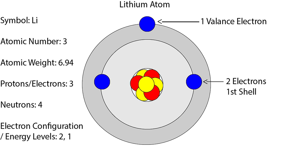
Atoms are the fundamental building blocks of matter, forming everything we see and interact with in the universe. Understanding their structure and behavior is essential for grasping key concepts in physics, chemistry, and material science.
Atoms are the foundation of all materials. Their structure, electron configuration, and bonding behavior determine whether a substance will conduct electricity, participate in chemical reactions, or act as an insulator. Grasping these principles is crucial for advancements in science and technology.
1. Structure of an Atom
As shown in illustration #1, atoms consist of three primary subatomic particles:
-
Protons: Positively charged particles located in the nucleus.
-
Neutrons: Neutral particles also found in the nucleus.
-
Electrons: Negatively charged particles that orbit the nucleus in energy levels or shells.
The nucleus, composed of protons and neutrons, accounts for most of an atom’s mass, while electrons determine an atom’s chemical properties.
2. Atomic Number and Mass Number
-
Atomic Number (Z): Represents the number of protons in an atom and determines the element.
-
Mass Number (A): The sum of protons and neutrons in the nucleus.
Atoms of the same element can have different numbers of neutrons, forming isotopes.
3. Electron Configuration and Energy Levels
Electrons orbit the nucleus in specific energy levels:
-
The first shell holds up to 2 electrons.
-
The second shell holds up to 8 electrons.
-
Higher shells can accommodate more electrons based on quantum mechanics.
Electrons in the outermost shell are called valence electrons, and they play a crucial role in chemical bonding and electrical conductivity.
4. Ions: Atoms with Different Numbers of Electrons and Protons
While neutral atoms have the same number of electrons as protons, atoms can gain or lose electrons, becoming ions:
-
Cations: Positively charged ions that have fewer electrons than protons.
-
Anions: Negatively charged ions that have more electrons than protons.
This imbalance between protons and electrons significantly influences an atom's chemical behavior, especially in forming compounds and conducting electricity.
5. Conductors, Semiconductors, and Insulators
Different materials have unique atomic structures that affect their ability to conduct electricity.
-
Conductors (Example: Copper (Cu)):
-
Copper atoms arrange in an orderly lattice.
-
They have loosely bound valence electrons that can move freely, allowing electricity to flow with minimal resistance.
-
Used in wires, electrical circuits, and conductors.
-
-
Semiconductors (Example: Silicon (Si)):
-
Silicon has a crystalline structure where valence electrons are normally bound.
-
Conductivity can be controlled by doping (adding impurities like phosphorus or boron).
-
Used in transistors, microchips, and diodes.
-
-
Insulators (Example: Rubber or Glass):
-
Insulators have strong covalent bonds and full valence shells, preventing electron movement.
-
Materials like silicon dioxide (SiO₂) or plastics are used in wire coatings and circuit protection.
-
Conductors, Semiconductors, and Insulators in Electronics
Conductors, Semiconductors, and Insulators in Electronics-
How They Work Together in Electronics
-
Conductors (Copper) → Transport electricity efficiently (wires, connections).
-
Semiconductors (Silicon) → Control electricity (transistors, microchips).
-
Insulators (Rubber, Plastic) → Prevent unwanted electrical flow (wire coatings, circuit boards).
Conductors
Copper Atom

Illustration #2
Electrical conductivity depends on how easily electrons can move through a material. This depends on the atomic structure, particularly the behavior of valence electrons (the outermost electrons).
1. The Role of Energy Bands in Conductors:
In solids, especially in conductors (like metals), atoms are arranged in a lattice structure, meaning the atoms are closely packed together. The electrons in these atoms don’t behave the same way as individual isolated atoms.
2. Conductors (Example: Copper (Cu))
-
Conductors Definition: Materials that allow electric current to flow easily because their electrons can move freely.
-
Why They Conduct Well:
-
As depicted in illustration 2, copper has one weakly bound valence electron in the 4s orbital that moves freely between atoms.
-
The atomic structure forms a metallic bond, creating a “sea of electrons” that allows charge to flow with low resistance.
-
-
Use in Electronics:
-
Copper is widely used in wires, circuit boards, and electrical contacts due to its high conductivity and low energy loss.
-
Other conductors: Silver (Ag), Gold (Au), and Aluminum (Al).
-
Semiconductors
Illustration #3

Semiconductors (Example: Silicon (Si))
Definition: Materials that have moderate conductivity, between conductors and insulators. Their conductivity can be controlled by adding impurities (doping) or applying voltage.
Why They Conduct Sometimes
-
Crystalline Structure: Silicon has 4 valence electrons, forming a crystalline structure where electrons are not free to move unless energy is applied.
-
Doping: By doping with elements like phosphorus (adds extra electrons) or boron (creates electron holes), silicon becomes more conductive.
Use in Electronics
Silicon components like transistors and diodes are the backbone of modern electronics, enabling the functionality of countless devices by controlling and amplifying electrical signals. Silicon is the foundation of modern electronics, used in transistors, diodes, and microchips to control electrical signals. How transistors and diodes work:
Transistors
Transistors are semiconductor devices that can act as switches and amplifiers. They are made from silicon and doped with impurities to create two types of regions: N-type (negative) and P-type (positive). Here’s how they function:
-
Switches: Transistors can turn electrical signals on and off.
-
When a small voltage is applied to the gate (in a MOSFET) or base (in a BJT), it controls the current flowing between the source and drain (MOSFET) or collector and emitter (BJT).
-
This allows the transistor to act as an on/off switch, enabling the control of large currents with small input signals.
-
-
Amplifiers: Transistors can amplify electrical signals.
-
A small input voltage at the gate/base can control a much larger current between the source-drain/collector-emitter.
-
This amplification capability is crucial in audio and radio frequency applications, where weak signals need to be amplified to usable levels.
-
Diodes
Diodes are semiconductor devices that allow current to flow in one direction only. They are made by joining N-type and P-type silicon to form a P-N junction. Here’s how they function:
-
Rectification: Diodes convert alternating current (AC) to direct current (DC).
-
When the positive end of an AC signal is applied to the P-side of the diode, it allows current to flow through.
-
When the negative end of the AC signal is applied to the P-side, it blocks the current.
-
This rectifying behavior is used in power supplies to convert AC from the wall outlet to DC required by electronic devices.
-
-
Switching: Diodes act as switches in circuits.
-
When forward-biased (positive voltage on P-side), they conduct current.
-
When reverse-biased (negative voltage on P-side), they block current.
-
This switching ability is used in signal processing and digital logic circuits.
-
Other Types of Semiconductors
-
Germanium (Ge): Used in high-speed transistors and diodes.
-
Gallium Arsenide (GaAs): Used in high-frequency applications like microwave and RF circuits.
Insulators
Composition of Insulating Materials:
Glass
-
Composition: Glass is primarily composed of silicon dioxide (SiO₂), also known as silica. It may also contain other oxides such as sodium oxide (Na₂O), calcium oxide (CaO), and aluminum oxide (Al₂O₃) to modify its properties.
-
Properties: Glass is a hard, brittle material that is transparent and has excellent insulating properties. It is used in applications like windows, laboratory equipment, and insulation for electrical conductors.
Rubber
-
Composition: Rubber can be natural or synthetic. Natural rubber is made from the latex of rubber trees (mainly polyisoprene), while synthetic rubber is derived from petrochemicals (e.g., styrene-butadiene rubber).
-
Properties: Rubber is flexible, waterproof, and has excellent insulating properties. It is used for insulation of wires.
Plastic
-
Composition: Plastics are polymers made from various monomers such as ethylene, propylene, and vinyl chloride. Common types include polyethylene (PE), polypropylene (PP), and polyvinyl chloride (PVC).
-
Properties: Plastics are versatile, lightweight, and have good insulating properties. They are used in a wide range of applications including insulation for wires and cables.
Ceramic
-
Composition: Ceramics are made from inorganic, non-metallic materials. Common ceramic materials include alumina (Al₂O₃), zirconia (ZrO₂), and silicon carbide (SiC).
-
Properties: Ceramics are hard, brittle, and highly resistant to heat and electricity. They are used in high-voltage insulators.
Insulators vs. Conductors
-
Complex Composition: Unlike conductors, which often have simpler compositions (e.g., metals like copper with a regular lattice structure), insulators require a more complex composition. This complexity ensures that their electrons are tightly bound to their atoms, preventing the free flow of electricity.
-
Full Valence Shells: Insulators have full valence shells, meaning there are no free electrons available to carry current.
-
High Energy Requirement: Electrons in insulators need very high energy to move, making these materials highly resistant to electricity.
Each of these insulating materials has unique properties that make them suitable for various applications, ensuring they effectively prevent the flow of electrical current.
Functions of Electrical / Electronic Components
Each electronic component serves a specific electrical function in an electronic circuit. Components are designed to either control, store, or convert electrical energy. Below is an overview of the key electrical functions of common electronic components:
1. Conducting Electricity: The Pathway for Current
Conductors are materials that allow electricity to flow easily. The most commonly used conductors in electronics are metals, which provide a low-resistance path for electrical current.
-
Copper: Widely used for wiring and circuit traces due to its excellent conductivity.
-
Gold: Used in connectors and pins for its resistance to corrosion and high conductivity.
-
Silver: Used in high-performance connectors for its superior conductivity.
These components don’t change the current itself but simply allow it to flow freely through the circuit.
2. Controlling Current Flow: Managing Electricity in Circuits
Some components are designed to limit or control the flow of electrical current to ensure circuits operate safely and efficiently.
-
Resistors: These components resist the flow of current, limiting the amount of electricity passing through. They help control voltage levels and prevent damage to other components.
-
Example: Carbon resistors, metal oxide resistors.
-
-
Transistors: Acting as switches or amplifiers, transistors control the flow of current between two points. They are essential in digital circuits and serve as the building blocks for logic gates and microprocessors.
-
Example: Bipolar junction transistors (BJTs), field-effect transistors (FETs).
-
-
Switches: These components open or close circuits, controlling whether current flows to connected devices.
-
Example: Toggle switches, push-button switches.
-
3. Storing Electrical Energy: Temporary Power Storage
Certain components store electrical energy temporarily and release it when needed.
-
Capacitors: These components store electrical energy in an electric field and can discharge it quickly when required. Capacitors are often used to smooth voltage fluctuations, filter signals, and provide backup power.
-
Example: Ceramic capacitors, electrolytic capacitors.
-
4. Converting Energy: Transforming Electrical Power into Other Forms
Some components convert electrical energy into other forms of energy, such as light, sound, or motion.
-
Light Emitting Diodes (LEDs): LEDs convert electrical energy directly into light. They are widely used for display screens, indicator lights, and in modern lighting applications because of their energy efficiency.
-
Example: Standard LEDs, OLEDs.
-
-
Speakers: Speakers convert electrical signals into mechanical motion, which in turn produces sound. The electrical current passes through a coil of wire in a magnetic field, causing the speaker cone to move and create sound waves.
-
Example: Dynamic speakers, piezoelectric speakers.
-
5. Directing the Flow of Current: Managing the Path of Electricity
Some components control the direction of electrical current, allowing it to flow in only one direction or redirect it under specific conditions.
-
Diodes: Diodes allow current to flow in only one direction, making them essential for converting alternating current (AC) to direct current (DC), as in power supplies. They are also used for protection in circuits by blocking reverse currents.
-
Example: Rectifier diodes, Zener diodes, Light Emitting Diodes (LEDs).
-
6. Protecting the Circuit: Safeguarding Against Excess Power
Protective components are used to prevent damage to circuits from excessive current or voltage.
-
Fuses: A fuse is a safety component that breaks the circuit when the current exceeds a certain level. This prevents overheating and damage to sensitive components.
-
Example: Glass fuses, ceramic fuses.
-
-
Varistors: Varistors are used to protect against voltage spikes by changing their resistance according to the voltage applied. They help safeguard against power surges.
-
Example: Metal oxide varistors (MOVs).
-
7. Conducting Sound: Converting Electrical Signals into Sound
-
Speakers: As mentioned above, speakers play a key role in converting electrical energy into audible sound. The electric current in the speaker’s coil interacts with the magnetic field, causing the diaphragm to vibrate and produce sound waves.
-
Example: Speaker drivers, subwoofers.
-
8. Transforming Voltage: Changing Power Levels
Transformers are electrical devices used to increase or decrease the voltage of alternating current (AC) in a circuit. They work on the principle of electromagnetic induction, where an electric current in one coil of wire generates a magnetic field that induces a current in another coil.
-
Step-up Transformers: Increase the voltage from the primary coil to the secondary coil, which is useful for transmitting power over long distances with minimal energy loss.
-
Example: Power transmission transformers.
-
-
Step-down Transformers: Decrease the voltage for safe usage in consumer electronics, ensuring that the voltage is appropriate for devices like televisions, chargers, and other household electronics.
-
Example: Adapter transformers for chargers.
-
Transformers do not work with direct current (DC) and are designed for use with AC to adjust power levels as needed.
9. Inducing Magnetic Fields: Storing and Controlling Energy
Coils (or Inductors) are components made by winding wire into loops or coils. They store energy in the form of a magnetic field when current flows through them. Coils resist changes in the current flow, making them essential for applications involving AC signals or filtering.
-
Inductors: These are primarily used to filter signals, smooth current, and store energy in magnetic fields. Inductors can be found in power supplies, transformers, and radio frequency circuits.
-
Example: Power supply filters, inductors in radio circuits.
-
-
Chokes: A specific type of inductor used to block high-frequency AC signals while allowing DC signals to pass.
-
Example: Power line filters, noise suppression in audio equipment.
-
Coils function by generating magnetic fields in response to the electric current and are key to many signal-processing applications, including signal filters, energy storage, and even wireless power transmission.
Active vs. Passive Components: Key Differences Explained
Components are often arranged by types and categories for various reasons:
The classification into active and passive components primarily serves an educational purpose. It's a foundational concept introduced to students and newcomers in the field of electronics to help them understand basic principles such as energy flow, signal amplification, and circuit behavior. Once these fundamentals are grasped, engineers and technicians move on to more detailed and application-specific considerations.
Active vs. Passive Electronic Components
In electronic circuits, components are broadly classified into two categories: active and passive. Understanding the distinction between these types is fundamental to circuit design and analysis.
Active Components
Definition: Active components are devices that can control the flow of electricity. They require an external power source to operate and can amplify signals or provide power gain.
Key Characteristics:
-
Energy Control: Capable of controlling electron flow and amplifying signals.
-
External Power: Require an external power supply for operation.
-
Signal Amplification: Can increase the power of a signal.
-
Non-linear Response: Exhibit non-linear voltage-current characteristics.
Common Examples:
-
Transistors: Used for amplification and switching.
-
Diodes: Allow current to flow in one direction.
-
Integrated Circuits (ICs): Complex assemblies performing various functions.
-
Operational Amplifiers (Op-Amps): Amplify voltage signals.
Passive Components
Definition: Passive components are devices that do not require an external power source to operate. They cannot amplify signals but can store or dissipate energy.
Key Characteristics:
-
Energy Storage: Store energy in electric or magnetic fields.
-
No Amplification: Cannot increase signal power.
-
Linear Response: Exhibit a linear relationship between voltage and current.
-
Bidirectional: Operate the same way regardless of current direction.
Common Examples:
-
Resistors: Limit current flow and divide voltages.
-
Capacitors: Store and release electrical energy.
-
Inductors: Store energy in a magnetic field.
-
Transformers: Transfer electrical energy between circuits.
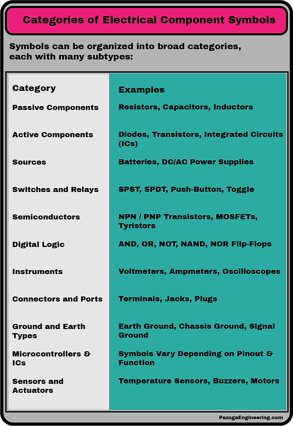
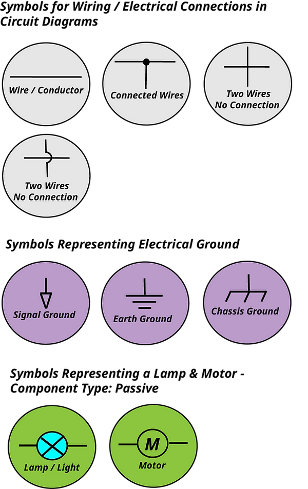
Categories of Electrical Component Symbols
Electrical component symbols are organized into functional categories, helping learners and engineers quickly identify the purpose and behavior of each symbol in a circuit diagram. These categories broadly reflect whether a component is discrete (simple, standalone function) or integrated (complex, multi-functional chip).
1. Discrete Components
Discrete components are individual parts that perform one basic function such as resisting current, storing charge, or switching signals. They are the building blocks of circuits and are commonly found in both learning environments and practical applications.
Examples Include:
-
Resistors – limit electrical current
-
Capacitors – store and release electrical energy
-
Inductors – store energy in a magnetic field
-
Diodes – allow current to flow in one direction
-
Transistors – amplify or switch signals
-
LEDs – emit light when current flows
-
Fuses – protect circuits from overcurrent
-
Switches – open and close circuits
Key Features:
-
Standalone parts with 2 or 3 leads
-
Easy to replace or test
-
Used in basic, hobbyist, and analog circuits
Integrated Components (ICs)
Integrated components, also known as Integrated Circuits (ICs), are self-contained packages that combine multiple electronic functions—often entire circuits—onto a single chip. ICs are essential in modern electronics, from smartphones to robotics.
Examples Include:
-
Operational Amplifiers (Op-Amps) – amplify voltage signals
-
Microcontrollers (e.g., ATmega328) – mini-computers on a chip
-
Logic Chips (e.g., 7400 series) – perform digital operations
-
Voltage Regulators (e.g., 7805) – provide stable output voltage
-
Memory Chips (EEPROM, Flash) – store digital data
-
Sensor Modules – measure temperature, light, distance, etc.
Key Features:
-
Contain dozens to millions of transistors
-
Perform complex tasks like computation, timing, or communication
-
Packaged in DIP, SOIC, QFP, or BGA forms
-
Pin counts range from 8 to 1000+
Electrical Components Can Be Placed into Various Categories
Understanding Electrical Component Symbols
Whether you're just starting out in electronics or want to sharpen your foundational knowledge, understanding electrical component symbols and schematics is essential. These two elements are the universal language of circuit design, allowing engineers, hobbyists, and students to communicate and build complex electronic systems with clarity.
What are Electrical Component Symbols?
Electrical component symbols are standardized graphical representations used to depict individual electronic components in circuit diagrams (schematics). These symbols make it possible to draw complex circuits in a compact and easy-to-understand way.
Instead of drawing a photo-realistic picture of a part, we use a symbol that represents the function of that component. These symbols are governed by international standards such as:
-
IEC (International Electrotechnical Commission)
-
ANSI (American National Standards Institute)
Why Use Symbols?
-
Universal understanding: Anyone familiar with electronics can read and understand the circuit.
-
Clarity: Symbols simplify complex circuits, especially when there are many components.
-
Efficiency: It’s quicker and easier to draw and edit designs.
How Many Electrical Component Symbols Are There?
There’s no exact number of electrical symbols, as the list continues to grow and evolve. However, when you include all the variations used in electronics and electrical engineering, there are hundreds of recognized component symbols.
Two major standards specify component symbols:
-
IEC 60617 (International standard) defines over 1,900 symbols.
-
ANSI Y32.2 / IEEE 315 (American standard) also has hundreds of symbols, many of which differ slightly from IEC versions.
In formal catalogs, there are well over 1,000 symbols, especially if you count:
-
Each type of switch and relay (latching, momentary, multi-pole, etc.)
-
Every variation of transistor (BJT, FET, IGBT, etc.)
-
Specific use-case symbols (fuses, circuit breakers, timers, etc.)
For Learners and Hobbyists
For most beginners, learning 30–50 core symbols is enough to:
-
Read most schematics
-
Understand common circuits
-
Start building your own projects
Common Electrical Component Symbols
Here’s a table of some of the most widely used components and their standard symbols:


The Fundamentals of Electronics:
Component Specifications, Schematics,
Circuit Board / Wiring Layouts & Bill of Materials
Understanding the fundamentals of electrical and electronic documentation is essential for designing and assembling reliable circuits. From component specifications that define electrical characteristics to detailed schematics that illustrate circuit functionality, every drawing, illustration, list, and specification plays a crucial role in engineering. Well-organized circuit board and wiring layouts ensure efficiency, signal integrity, and manufacturability, while a structured bill of materials (BOM) streamlines procurement and assembly. By mastering these various forms of documentation, engineers and enthusiasts can create optimized electronic systems tailored to specific applications.
Electrical Component Specifications:
Defining Functionality & Physical Characteristics
Electrical component specifications outline the essential properties that determine a component's performance, compatibility, and reliability within an electronic circuit. These specifications ensure that the component operates safely and effectively under expected conditions.
Key Aspects of Electrical Component Specifications
1. Electrical Characteristics
Each component has electrical parameters that define how it interacts within a circuit:
-
Voltage Rating – Maximum voltage the component can handle safely.
-
Current Rating – Defines the maximum allowable current before risk of damage.
-
Resistance, Capacitance, & Inductance – Governs passive electrical behavior.
-
Power Dissipation – Specifies how much power a component can safely dissipate.
-
Signal Characteristics – Includes frequency response, propagation delay, and noise levels.
2. Mechanical Specifications
Since electrical components exist as physical objects, they come with mechanical parameters that affect installation and durability:
-
Dimensions & Form Factor – Size and shape, ensuring proper fit within designs.
-
Material Composition – Impacts thermal conductivity, insulation, and longevity.
-
Lead & Terminal Configuration – Determines how the component connects electrically.
-
Environmental Ratings – Resistance to temperature extremes, moisture, and mechanical stress.
A well-documented component specification allows engineers to select the right parts, ensuring efficiency, longevity, and proper operation within an electrical system. Whether designing a simple circuit or a complex electronic device, understanding both electrical and mechanical specifications is crucial for achieving optimal performance.
Example of Manufacturers Specifications

The Evolution of Schematic Diagrams:
From Hand-Drawn Blueprints to Digital Designs
Origins and Early Development
Schematic diagrams have long been fundamental tools in electrical and electronic engineering, providing a visual representation of circuits using standardized symbols to denote components and lines to indicate connections. In the early days of electrical engineering, these diagrams were meticulously hand-drawn, serving as essential blueprints for constructing and understanding complex systems.
Traditional Drafting Techniques
Before the advent of computer-aided design (CAD) tools, schematics were created manually using precision instruments. Engineers and draftsmen employed tools such as T-squares, compasses, and technical pens to draw accurate and detailed diagrams. These drawings were typically made on durable materials like vellum or drafting linen, which could withstand repeated handling and reproduction.
To replicate these schematics, techniques like blueprinting and diazo printing were used, allowing for multiple copies to be distributed for manufacturing and maintenance purposes. The clarity and precision of these hand-drawn schematics were paramount, as they directly influenced the reliability of the resulting electronic systems.
Transition to Digital Methods
The introduction of CAD software revolutionized the creation of schematic diagrams. Starting in the late 20th century, engineers began using digital tools to design and edit schematics, significantly improving efficiency and accuracy. Software applications allowed for easy modifications, error checking, and integration with other design processes, such as printed circuit board (PCB) layout and simulation.
This digital shift also facilitated better collaboration among engineering teams, as electronic files could be easily shared and updated in real-time, reducing the likelihood of errors and streamlining the development process.
Contemporary Practices
Today, schematic diagrams are predominantly created using advanced electronic design automation (EDA) tools. These platforms offer a range of features, including component libraries, real-time collaboration, and integration with simulation and PCB design modules. Modern schematics are often stored in standardized digital formats, ensuring compatibility across different software and facilitating seamless communication among engineers worldwide.
Furthermore, the use of standardized symbols and notation, governed by international standards, ensures that schematics are universally understood, regardless of the engineer's location or language. This global standardization is crucial for the efficient development and maintenance of electronic systems in our interconnected world.
What Are Schematics?
Electrical Schematic Definition:
A schematic diagram is a standardized visual representation of an electronic circuitry, using symbols to depict components and lines to illustrate electrical connections. Unlike physical layouts, schematics focus only on the specific components used, and how they are connected together.
Just as a writer drafts a novel or a musician composes a new song, an engineer designing a circuit needs a way to capture their ideas on paper. This process of putting something on paper allows for visualization, examination, and modification, and the means to document and share the idea of the new circuit design.
These creative endeavors, be it writing a book, composing a song, or developing a new circuit, require brainstorming, visualized documentation of the idea, evaluation, and building on your original idea, and honing it, until you believe that you have created a work of art, or a functional circuit...
For engineers, translating an abstract idea into a functional circuit involves more than just inspiration; it demands a structured approach. By documenting designs through schematics, engineers can visualize complex systems, identify potential issues, and iteratively improve their creations. This methodical process ensures that intricate designs are thoroughly understood and effectively communicated, much like how authors and musicians meticulously develop their works overtime.
Schematic diagrams are essential for documenting and sharing circuit designs. By adhering to international standards such as IEC 60617 and ANSI Y32 (IEEE 315), schematics ensure consistency and clarity across different regions and industries. This standardization allows engineers worldwide to interpret and collaborate on designs effectively, regardless of language or location.
A schematic tells you:
-
What components are in the circuit
-
How they are connected (serial, parallel, etc.)
-
Where current flows and how signals are processed
Below is the schematic diagram of my LED American Flag design. When designing circuits intended for printed circuit boards (PCBs), engineers often arrange components in the schematic to reflect their anticipated physical placement on the board. This approach facilitates a smoother transition from schematic to PCB layout.
However, this method isn't always applicable. In scenarios where components are connected using wires rather than a PCB, such as in residential or commercial electrical systems, the schematic fucuses on circuit design, configuration, not on physical placement. For instance, a schematic might depict a light switch adjacent to a light fixture, but in reality, they could be separated by 200 feet. Schematics purpose is as visual aid, in understanding the system's functionality without being constrained by physical layouts.
It's important to remember that schematic diagrams serve as conceptual representations, focusing on the electrical relationships between components. They are not intended to mirror the actual physical arrangement of components in the final implementation.
Understanding Schematic Design Software:
Free vs. Professional Options
Schematic design software is a powerful tool for creating, analyzing, and documenting electronic circuits. While engineers have long used graph paper and drafting techniques to sketch circuit designs, and this method is still perfectly legitimate for many applications, software offers very significant clear advantages.
These digital tools help visualize electrical connections in a clean, scalable format and allow for seamless transitions to PCB layout, circuit simulation, and documentation. For simple or early-stage designs, hand-drawn schematics may be sufficient. But when it comes to refining your work, collaborating with others, or preparing for manufacturing, schematic software is a complete game-changer.
More than just a digital convenience, schematic software has become a cornerstone of modern design. It enables seamless transitions to PCB layout, supports circuit simulation, and simplifies documentation, making it indispensable for refining ideas, collaborating with others, and moving confidently toward manufacturing.
For anyone looking to design efficient, professional-quality electronics, these tools aren’t just helpful, they’re transformative.
.
Different Uses of Schematic Design Software
The same software can be used for multiple purposes, including:
-
Schematic Capture – Drawing circuit diagrams with standardized symbols.
-
Simulation – Testing circuit behavior before physical implementation.
-
PCB Layout Integration – Transitioning schematics into board designs.
-
Component Specification & BOM Generation – Organizing parts for manufacturing.
-
Collaboration & Documentation – Sharing designs and generating reports.
Free vs. Professional Schematic Design Software
There are free and professional schematic design tools available, each with different capabilities.
Free Schematic Design Software
These tools are great for beginners, students, and small-scale projects:
-
KiCad – Open-source, widely used by professionals, supports multi-layer boards and 3D visualization.
-
EasyEDA – Web-based, integrates with JLCPCB for manufacturing, ideal for quick prototyping.
-
Fritzing – Best for beginners and educational use, but not ideal for complex circuit designs.
-
DesignSpark PCB – Free software with advanced features, suitable for hobbyists and small businesses.
-
LTspice – Focused on circuit simulation, widely used for analog designs.
Professional Schematic Design Software
These tools are used in industry for high-end circuit design and analysis:
-
Altium Designer – Industry-leading software with advanced schematic capture, simulation, and PCB integration.
-
Autodesk Eagle – Popular among engineers, offers schematic capture and PCB layout with simulation tools.
-
Cadence OrCAD – Used for high-speed circuit design, signal integrity analysis, and large-scale projects.
-
Mentor Graphics PADS – Advanced schematic and PCB design software for professional engineers.
-
Proteus – Combines schematic capture with real-time simulation for embedded systems.
Choosing the Right Schematic Design Software
-
Beginners & Hobbyists → EasyEDA, Fritzing, DesignSpark PCB
-
Students & Small Businesses → KiCad, LTspice, Eagle (Free Version)
-
Professional Engineers → Altium Designer, OrCAD, Proteus
Each software has unique strengths—some focus on simulation, while others emphasize PCB integration. The best choice depends on your project complexity, budget, and experience level.
Why I Chose Free EasyEDA Software
When I set out to design my American Flag Soldering Kit, which I'm offering as a free download on this website, I needed software to help bring the idea to life. Out of all the options available, I ultimately chose the free EasyEDA software, and I’d like to share why.
If I were working for a company or developing a commercial product, I would have chosen one of the top-tier professional design tools. But in my case, I’m retired, and this design isn’t intended for commercial use or any application where intellectual property protection would be a concern. It’s simply a personal hobby project that I’m offering as a free resource. So, my goal was straightforward: to find a no-cost solution that could still deliver a professional-quality result.
Like most people, I began by researching online, and saw numerous YouTube videos, promoting free EasyEDA software, it appeared to be widely used by electronics enthusiasts. EasyEDA stood out as a popular and well-supported option in the hobbyist community. Since it was free, I had nothing to lose by giving it a try.
Interestingly, I didn’t initially need the schematic capture feature in EasyEDA, as my design was extremely simple, and I had already laid out my schematic on graph paper. As a longtime engineer, I was comfortable sketching out my circuit by hand on graph paper, just as engineers have done for decades before computers existed. Creating schematics on paper is still a perfectly valid approach.
I only began looking for software when I decided to turn my idea into a physical product, something that required a printed circuit board (PCB). The fact that EasyEDA lets you design both schematics and PCBs was a bonus, but for my purpose, the PCB layout tool was really all I needed.
After working with EasyEDA, I’ve been thoroughly impressed. The features, learning curve, and component library are all excellent. Even the support for complex multi-layer boards (up to 18 layers) is remarkable for free software.
In my opinion, EasyEDA is a fantastic choice for electronics hobbyists and may even be suitable for some limited professional use, as long as intellectual property isn’t a concern.
And to complete the process, I also chose JLCPCB to fabricate my prototypes. Their service integrates seamlessly with EasyEDA, making the transition from digital design to physical board quick and affordable.
What You Should Know:
EasyEDA is primarily a cloud-based platform, which means your projects are stored on their servers unless you explicitly choose to download and manage them locally. While this makes collaboration and access from any device convenient, it also raises valid concerns about intellectual property (IP) protection.
-
By default, your designs are saved to EasyEDA’s servers, which are operated by JiaLiChuang (Hong Kong) Co., Ltd.—the same company behind JLCPCB and LCSC.
-
You can choose to make your projects private or public. Private projects are not visible to others, but they still reside on EasyEDA’s infrastructure.
-
According to their Terms of Service, you retain ownership of your content, but by using the platform, you grant them certain rights to host and display your work as needed to provide the service.
-
They also have a complaints and appeal process for IP infringement, which suggests they take IP concerns seriously—but enforcement and transparency may vary.
JLCPCB (short for "JiaLiChuang PCB") is one of the world’s largest and most affordable PCB fabrication and assembly services. Founded in 2006, it offers:
-
Prototype and mass production of PCBs (1–32 layers)
-
Surface-mount (SMT) and through-hole (THT) assembly
-
Fast turnaround times—as quick as 24 hours for fabrication
-
Support for rigid, flex, aluminum, and high-frequency boards
-
Seamless integration with EasyEDA for direct ordering
JLCPCB is known for its low pricing, automated smart factories, and global shipping, making it a go-to for hobbyists and startups alike. You can explore their services atjlcpcb.com.
LCSC
LCSC is a component distributor that stocks over 560,000+ electronic parts, including resistors, capacitors, ICs, connectors, and more. It’s essentially the parts-sourcing arm of the same ecosystem:
-
Offers competitive pricing on both common and hard-to-find components
-
Integrates directly with EasyEDA and JLCPCB for BOM import and sourcing
-
Ships globally with options for bulk orders or prototyping quantities
-
Supports component traceability and datasheet access
You can browse their catalog atlcsc.com
How They Work Together
When you design a circuit in EasyEDA:
-
You can source components from LCSC directly within your BOM.
-
You can order PCBs and assembly from JLCPCB with just a few clicks.
-
The integration allows for streamlined manufacturing, reducing errors and lead time.
This trio—EasyEDA, JLCPCB, and LCSC—offers a nearly end-to-end solution for electronics development, from design to delivery.
Example of a Schematic Diagram
Created Using Free EasyEDA Software

Turning Your Schematic to PCB 3D Layout Assembly In
EasyEDA
Once your schematic is complete in EasyEDA, the next step is to transform that logical design into a physical Printed Circuit Board (PCB) layout, and ultimately visualize it as a 2D and 3D assembly. This process bridges the gap between concept and manufacturable hardware.
3D Illustration of My LED Flag Circuit Board Design
Below are two 3D rendering of the topside & bottom-side of my LED Flag Circuit Board that I created using EasyEDA, a free and user-friendly electronic design automation (EDA) tool that incorporates schematic layout, circuit simulation, and PCB layout. EasyEDA offers both 2D and 3D PCB visualizations, allowing the user to see a visual layout illustration of their circuit board design.
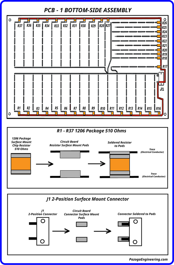
Please note: These illustrations below represent the topside & bottom-side, of a two-layer printed circuit board (PCB). In this design, LEDs are mounted on the top side, while surface-mount resistors are placed on the bottom side. All copper traces are only the bottom-side of PCB, in this simple design. EasyEDA supports up to 34 copper layers with its PCB design software.
3D Rendering Circuit Board Topside
Illustrating LED Components
.png)
3D Rendering Circuit Board Bottom-Side
Illustrating Surface Mount Resistors and Copper Traces
.png)
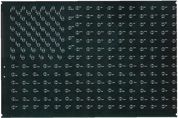
Below is the Topside View of the Actual Circuit Board
Note: Many circuit board manufacturers offer boards in a variety of colors based on customer preference. The board's color has no impact on its electrical operation, as it is merely the pigment of the epoxy material. Engineers select colors according to personal preference. I choose to use black-pigmented circuit boards, as I believe black is best suited for this specific product and application, particularly for an LED display.
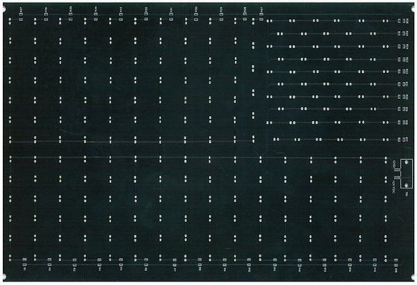
Bottom-Side View of Actual Circuit Board
Common Reference Designators Used for Circuit Board Components
These designators help identify components in schematics and their location on a Printed Circuit Board:
-
R – Resistor
-
C – Capacitor
-
L – Inductor
-
D – Diode (including LEDs and Zener diodes)
-
Q – Transistor
-
U – Integrated Circuit (IC)
-
J – Connector
-
K – Relay
-
S – Switch
-
T – Transformer
-
F – Fuse
-
Y – Crystal Oscillator
-
BT – Battery
-
TP – Test Point
-
PCB - Printed Circuit Board
Circuit Board Assembly

Electronics Manufacturing Engineers
Often Call Circuit Board Assembly -
Component Population

Illustration of Circuit Board Top-View
LEDs Component Location / Orientation for Assembly Purposes
Note: To simplify assembly, I opted to use LED colors to identify their locations rather than the standard reference designators.
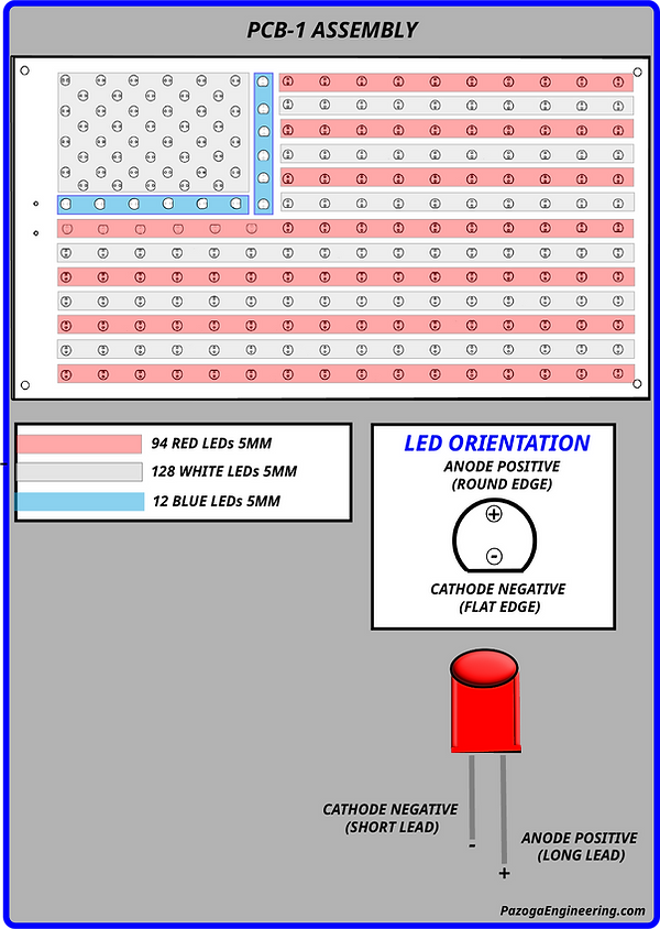
Illustration of Circuit Board Bottom-Side
Component Location for Assembly Purposes
Intellectual Property (IP) Basics

Understanding Intellectual Property Rights in Electrical Schematics
Electrical schematics are more than just technical drawings; they are the culmination of an engineer's creativity and expertise. As such, they are protected under various forms of intellectual property (IP) law, ensuring that creators can safeguard their work and control its use.
Copyright Protection
In many jurisdictions, including those adhering to the Berne Convention, schematic diagrams are protected under copyright law as "pictorial, graphic, and sculptural works." This protection arises automatically upon the creation of the schematic, without the need for formal registration. However, registering the work can provide additional legal benefits, such as the ability to seek statutory damages in infringement cases.
It's important to note that copyright protects the specific expression of an idea, not the idea itself. This means that while the particular arrangement and depiction of components in a schematic are protected, the underlying concepts or functions they represent are not.
Patent Considerations
If a schematic embodies a novel and non-obvious invention, it may be eligible for patent protection. A patent grants the holder exclusive rights to the functional aspects of the invention, preventing others from making, using, or selling the patented invention without permission. Obtaining a patent requires a formal application process and a thorough examination by the relevant patent office.
Trade Secrets
Some organizations choose to protect their schematics as trade secrets. This approach involves keeping the schematic confidential and implementing measures to prevent unauthorized disclosure. Unlike patents, trade secret protection does not require public disclosure, but it offers no protection if the information becomes publicly known through independent discovery or reverse engineering.
Mask Work Protection
For integrated circuit layouts, the Semiconductor Chip Protection Act (SCPA) in the United States provides protection for the three-dimensional layout designs, known as "mask works." This form of protection is similar to copyright but specifically tailored to semiconductor designs. It prevents unauthorized copying of the layout but does not protect the functional aspects of the circuit.
Practical Implications
Understanding the IP protections applicable to electrical schematics is crucial for engineers and organizations. It ensures that creators can defend their work against unauthorized use and helps maintain a competitive edge in the industry. Whether through copyright, patents, trade secrets, or mask work protection, safeguarding schematics is an essential aspect of modern engineering practice.
Units of Measure in Electrical and Electronic Systems
Understanding units of measure is essential when working with electricity and electronics. These units allow us to quantify physical properties, perform accurate calculations, and ensure safety and compatibility in circuits and systems. Most are based on the International System of Units (SI).
Below is a breakdown of the most important units used in the field:
1. Voltage (V)
-
Unit: Volt (V)
-
Symbol: V
-
What it measures: Electrical potential difference the "force" that pushes current through a circuit.
-
Common Prefixes:
-
mV – millivolt = 0.001 V
-
kV – kilovolt = 1,000 V
-
2. Current (I)
-
Unit: Ampere (A)
-
Symbol: A
-
What it measures: Flow of electric charge through a conductor.
-
Common Prefixes:
-
mA – milliampere = 0.001 A
-
μA – microampere = 0.000001 A
-
3. Resistance (R)
-
Unit: Ohm (Ω)
-
Symbol: Ω
-
What it measures: Opposition to the flow of current.
-
Related Law: Ohm’s Law → V = I × R
4. Power (P)
-
Unit: Watt (W)
-
Symbol: W
-
What it measures: Rate at which electrical energy is consumed or generated.
-
Formula: P = V × I
-
Common Prefixes:
-
mW – milliwatt
-
kW – kilowatt
-
MW – megawatt
-
5. Capacitance (C)
-
Unit: Farad (F)
-
Symbol: F
-
What it measures: Ability to store energy in an electric field.
-
Common Prefixes (often small values):
-
μF – microfarad
-
nF – nanofarad
-
pF – picofarad
-
6. Inductance (L)
-
Unit: Henry (H)
-
Symbol: H
-
What it measures: Ability to store energy in a magnetic field.
-
Common Prefixes:
-
mH – millihenry
-
μH – microhenry
-
7. Frequency (f)
-
Unit: Hertz (Hz)
-
Symbol: Hz
-
What it measures: Number of cycles per second (used in AC systems).
-
Example: 60 Hz (U.S. power), 50 Hz (many other countries)
8. Temperature (T)
-
Units: Degrees Celsius (°C) or Kelvin (K)
-
Used in: Semiconductors, thermistors, and component ratings
SI Prefixes Commonly Used in Electronics
These prefixes help express very large or very small values clearly and concisely:

Basic Battery Operation & Current Flow
When a copper wire is connected between the negative and positive terminals of a battery, electron flow begins as free electrons on the negative side push on the loosely bound valence electrons of the copper atoms, displacing them. This displacement creates a chain reaction of electrons moving through the wire toward the positively charged terminal of the battery, where they recombine with positively charged lithium-ion atoms.
Although this is the actual direction of electron movement, most circuit diagrams and electrical theories still use conventional current flow, which assumes current flows from the positive terminal to the negative. This convention dates back to early scientists who didn't yet understand the role of electrons, and it has remained in use for consistency across engineering and educational systems. Despite flowing in the opposite direction of real electrons, conventional current still accurately represents how circuits function.
Illustration #4

PazogaEngineering.com
As shown in Illustration # 4, in a copper wire, the outermost electrons of the copper atoms called valence electrons are loosely bound and free to move. When a battery is connected, these electrons are pushed off their atoms, leaving behind a positively charged "hole." That hole is quickly filled by another nearby electron, which is then displaced in turn. This creates a chain reaction of electrons pushing each other forward, moving toward the positive terminal of the battery. These free-moving electrons form what’s known as a "sea of electrons," allowing current to flow easily through the metal.
Electron Excitation and Movement:
In the absence of external energy (such as a battery), the electrons of copper atoms in the valence band typically remain stationary relative to their atoms. However, when an electric field (like the one applied by a battery) is introduced, the copper electrons experience a force that can push them away from their atoms.
-
External energy (such as a voltage applied across a conductor) provides enough energy to copper electrons to move them from the valence band into the conduction band.
-
In conductors like copper, the conduction band is only slightly higher in energy than the valence band, so electrons can easily move between atoms within the conductor when an electric field is applied.
The Movement of Electrons Between Atoms:
Once electrons are in the conduction band, they are free to move through the material. Here’s what happens when an electron "moves" from one atom to another:
-
Electron displacement: In a conductive material like copper, the outermost electrons don’t stay bound to individual atoms. Instead, these electrons move freely through the lattice of atoms.
-
When an electron moves from one atom to another, it effectively "leaves" its position in one atom and becomes part of the electron cloud of a neighboring atom.
-
The "hole" left behind by the electron in the original atom behaves as if it’s a positively charged particle, creating a positive charge region. At the same time, the electron in its new location carries a negative charge.
-
As more electrons move, current is established. The flow of these negatively charged electrons through the conductor is what we call electric current.
Collisions with Atoms (Resistance):
Even though electrons move freely in a conductor, they don’t travel in a straight line without interruptions. As they move, they collide with the atoms or ions in the conductor’s lattice structure.
-
These collisions cause the electrons to lose some of their kinetic energy, which is then transferred to the lattice atoms, causing them to vibrate and generate heat. This phenomenon is called resistance.
-
The more often electrons collide with atoms, the higher the resistance, and the more heat is generated.
Why does the movement of electrons cause heat?
When electrons flow through a conductor (like a wire), they don't just move smoothly and directly from one atom to another. Instead, they interact with the atoms in the material that they are traveling through.
Here's what happens:
1. Electron Movement and Collisions:
-
Electrons are constantly moving through the wire because of the voltage provided by a power source (like a battery). However, as they move, they collide with the atoms (or ions) in the conductor (like the copper atoms in the wire).
-
These collisions are not perfectly elastic; they cause the electrons to lose some of their kinetic energy (the energy of motion) during each interaction.
2. Transfer of Energy:
-
When the electrons collide with the atoms in the conductor, they transfer some of their energy to these atoms. This causes the atoms to vibrate more vigorously.
-
As the atoms vibrate more, the conductor’s temperature increases, which is what we perceive as heat.
3. Resistance and Heat:
-
The resistance of a material refers to its opposition to the flow of electric current. The higher the resistance of a material, the more collisions occur between the moving electrons and the atoms in the material.
-
More collisions mean more energy is transferred from the electrons to the atoms, which leads to more heat being generated.
-
In materials like copper, which are good conductors, there is less resistance, so less heat is produced. But if you use a material with higher resistance (like a piece of nichrome wire used in a heater), more collisions happen, resulting in more heat.
Understanding Circuits: Types and Their Functions
Circuit
A circuit is a complete and closed path through which electric current can flow. It typically consists of various electronic components such as resistors, capacitors, inductors, and power sources (like batteries), connected by conductive wires or traces. The fundamental purpose of a circuit is to allow the controlled flow of electric current to perform a specific function, such as lighting a bulb, powering a motor, or processing signals in electronic devices.
Short Circuit
A short circuit occurs when there is an unintended low resistance connection between the positive and the negative side of any power source. This direct connection bypasses the intended path of the circuit, resulting in a surge of current that can lead to various problems, including overheating, damage to components, and potential fire hazards.
Two examples of a short circuit:
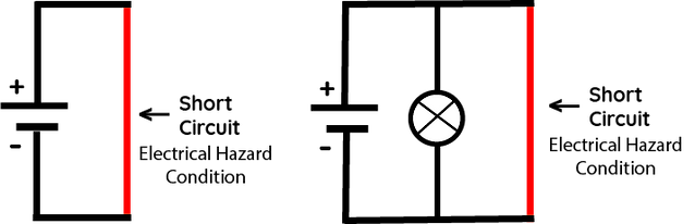
Series Circuit
A series circuit is a type of circuit in which components are connected end-to-end, forming a single path for current to flow. If one component fails or is disconnected, the entire circuit is interrupted.
Two examples of series circuits:

Parallel Circuit
A parallel circuit is a type of circuit in which components are connected across common points or junctions, forming multiple paths for current to flow. If one component fails, the current can still flow through the other paths.
Two examples of parallel Circuits:

Series-Parallel Circuit
A series-parallel circuit combines elements of both series and parallel circuits. Some components are connected in series, while others are connected in parallel.
Two examples of series / parallel circuits

A Beginner’s Guide to Voltage, Current, Resistance, and Power
Understanding Voltage, Current, Resistance, and Energy in Electrical Circuits
Electricity and electronics are all about the flow of energy. Understanding the key concepts that describe how this energy moves and is used is essential to grasp how devices function. At the heart of every electrical system are four important concepts: voltage, current, resistance, and power. These describe the way energy is controlled, transferred, and consumed in a circuit.
1. What is Voltage? (Symbol: V)
Voltage (also known as potential difference) is the measure of the potential energy per unit charge available to move electrons in a circuit. Essentially, voltage is the "push" or force that drives electric charge to flow through a conductor, such as a wire. It can be thought of as the electrical pressure that makes electrons move.
-
Unit of Measurement: Volt (V)
-
Formula for Voltage: V = E / q
-
Where:
-
V is voltage (in volts, V)
-
E is energy (in joules, J)
-
q is charge (in coulombs, C)
-
This formula shows that voltage is the energy available per unit of charge to drive the movement of current through a circuit.
2. What is Current? (Symbol: I)
Current is the flow of electric charge through a conductor. It represents the rate at which the electrons are moving through the circuit. The amount of current depends on the voltage and the resistance of the circuit.
-
Unit of Measurement: Ampere (A)
-
Formula for Current: I = q / t
Where:
-
I is current (in amperes, A)
-
q is charge (in coulombs, C)
-
t is time (in seconds, s)
This formula tells us that current is the rate at which charge flows through the circuit over time.
3. What is Resistance? (Symbol: R)
Resistance is the opposition that a material offers to the flow of electric current. It depends on the material’s properties, such as its length, cross-sectional area, and resistivity. Higher resistance means it is harder for the current to flow through the material.
-
Unit of Measurement: Ohm (Ω)
-
Formula for Resistance: R = V / I
Where:
-
R is resistance (in ohms, Ω)
-
V is voltage (in volts, V)
-
I is current (in amperes, A)
This formula comes from Ohm’s Law, which shows the relationship between voltage, current, and resistance in a circuit.
4. How Power and Energy are Related
When an electric device (like a light bulb or motor) is connected to a power source (such as a battery), it consumes electrical energy. The rate at which energy is used is called power.
-
Unit of Measurement: Watt (W)
-
Formula for Power: P= V x I
Where:
-
V is voltage (in volts, V)
-
I is current (in amperes, A)
-
P is power (in watts, W)
Power represents the amount of energy transferred or used per unit of time. One watt (W) is defined as one joule per second.
Understanding Watts and Joules
-
Watts (W): This is the unit of power. It tells you how much energy is being used each second. For example, a 60W light bulb uses 60 joules of energy every second.
-
Joules (J): This is the unit of energy. It tells you how much total energy is used or transferred over time. One joule is the energy used when one ampere of current flows through a resistance of one ohm for one second.
-
Coulombs (C): This is the unit of electric charge. One coulomb is the amount of charge transported by a current of one ampere (A) flowing for one second (s).
Total Energy Usage Over Time
To calculate how much total energy is used over a period of time, we need to factor in the duration for which the power is being consumed.
-
Formula for Energy (over time): E = P x t = (V x I) x t
Where:
-
E is energy (in joules, J)
-
P is power (in watts, W)
-
t is time (in seconds, s)
This formula tells us how much total energy (in joules) has been used by a device over a specific period of time. For instance, if a 60W light bulb is on for 1 hour (3600 seconds), it will consume:
E = 60W x 3600s = 216,000J
Key Units of Measure:
-
Voltage (V): Measured in volts (V)
-
Current (I): Measured in amperes (A)
-
Resistance (R): Measured in ohms (Ω)
-
Power (P): Measured in watts (W)
-
Energy (E): Measured in joules (J)
-
Charge (q): Measured in coulombs (C)
-
Time (t): Measured in seconds (s)
DC Power Sources - Batteries
Illustration #5
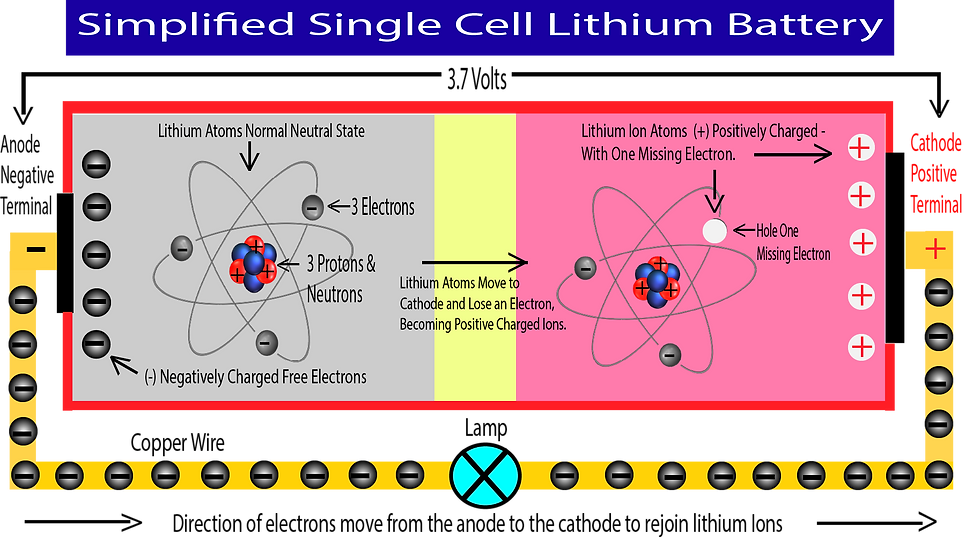
As per illustration #5, the operation of lithium batteries relies on the movement of lithium ions between the anode (negative side) and the cathode (positive side) through an electrolyte, generating electrical energy.
Simplified breakdown of the electrochemical process:
Anode:
Inside the battery, lithium atoms move from the anode to the cathode, where they lose an electron and become lithium ions (Li⁺). As the lithium ions migrate to the cathode, they leave behind free electrons, which accumulate on the anode side of the battery.
Cathode:
Lithium atoms that have moved from the anode become lithium ions and are intercalated into the cathode structure, meaning that they are then stored within the cathode material.
Intercalated meaning:
Inserted or layered into the structure of a material without breaking it apart. In this case, the lithium ions slip into the layers of the electrode material (like graphite for the anode or lithium cobalt oxide for the cathode) without damaging the material.
Discharge Process:
When an external circuit is connected, the free electrons from the anode flow through the circuit and arrive at the cathode, where they recombine with lithium ions to form neutral lithium atoms. As this electrochemical process continues, the battery is in the process of discharging. Once all the available electrons from the anode have traveled through the circuit, the battery is considered depleted, as the electrons have recombined with the lithium ions at the cathode, and the lithium atoms have returned to their normal, neutral state with a balanced charge.
Recharge Process (when the battery is being recharged):
Recharge Process:
When the battery is connected to an external power source (a charger), a voltage is applied in the opposite direction of the discharge flow. This electrical energy forces the electrons to move from the cathode back to the anode through the external circuit. At the same time, lithium ions (Li⁺) are pulled out of the cathode structure, traveling through the electrolyte back toward the anode.
When the lithium ions reach the anode, they recombine with the returning electrons to form neutral lithium atoms. These atoms are then intercalated into the layered structure of the anode material (typically graphite), effectively restoring the battery to a charged state.
This reverse movement of both ions and electrons reestablishes the conditions needed for another discharge cycle.
Lithium-ion Battery Characteristics
-
Voltage: Lithium-ion cells have a typical voltage of 3.7 volts.
-
Anode: Often made of graphite.
-
Cathode: Usually made of a lithium compound such as LiCoO2.
-
Electrolyte: A lithium-based solution that allows ions to flow between electrodes.
-
Energy Storage: Larger batteries store more energy due to more space for electrochemical reactions, increased electrode surface area, and larger amounts of electrolyte.
Lithium Batteries: Battery Cells, Electrochemistry, and Voltage
A battery is composed of one or more cells, each of which has its own electrochemical reaction that generates a voltage. The materials used for the electrodes and electrolyte in the cell determine the voltage and overall performance of the battery.
Battery Cell Structure
A simple battery cell includes:
-
Two electrodes: A positive electrode (cathode) and a negative electrode (anode).
-
Electrolyte: A conductive solution or paste that allows ions to flow between the electrodes.
The chemical reaction at each electrode creates a voltage that drives electrons through a connected external circuit. This flow of electrons is what powers electronic devices.
Voltage Generation in Batteries
The voltage of a battery is determined by the difference in chemical potential between the anode and cathode. The electrochemical reactions that occur at each electrode cause the movement of ions through the electrolyte, generating electrical energy.
For example:
-
Alkaline battery: A standard AA alkaline battery has a typical voltage of 1.5 volts, generated by a zinc anode and manganese dioxide cathode, with an alkaline electrolyte.
-
Lithium-ion battery: A common lithium-ion battery, like those used in electronics, has a typical voltage of 3.7 volts. This is due to a lithium compound at the anode (such as LiCoO2 or LiFePO4) and graphite at the cathode.
The difference in the chemical potential of these materials leads to different voltages for different types of batteries. Lithium-ion cells generate a higher voltage than alkaline batteries because of the specific electrochemical combination of materials.
Connecting Battery Cells in Parallel and Series:
Batteries in Parallel:
When battery cells are connected in parallel, the voltage remains the same, but the capacity (mAh or Ah) increases. The total capacity is the sum of the capacities of each individual cell, while the voltage stays constant.
Example:
-
If you connect two 3.7V, 2200mAh lithium-ion cells in parallel, the voltage remains 3.7V, but the total capacity will be 4400mAh.
Formula for Batteries in Parallel: Ctotal = C1 + C2 +⋯ + Cn
Where:
-
Ctotal is the total capacity.
-
C1, C2…, Cn are the capacities of the individual cells.
Examples of output voltage and amp-hour capacity of batteries connected in parallel:

Connecting Cells in Series
When multiple battery cells are connected in series, their voltages add up, but the current capacity in (mAh or Ah) does not increase. By combining single battery cells in series allows for the creation of higher voltages, but the total available current remains the same as a single battery.
Example:
-
If you connect two 3.7V, 2200mAh lithium-ion cells in parallel, the voltage remains 3.7V, but the total capacity will be 4400mAh.
-
Formula for Batteries in Series: Vtotal = V1 + V2 +⋯+ Vn
-
Where:
-
Vtotal is the total voltage of the series connection.
-
V1, V2…,Vn are the voltages of each individual cell.
-
Examples of output voltage and amp-hour capacity of batteries connected in series:
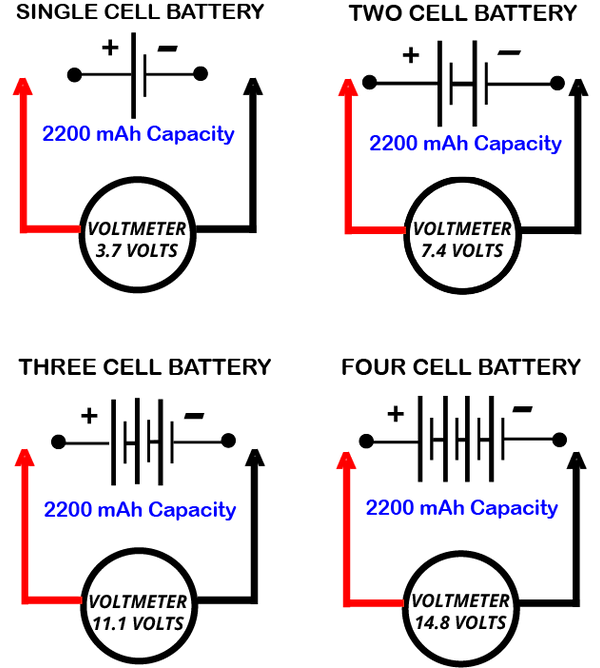
For example:
-
Two lithium-ion 3.7-cells in series will provide a total voltage of 7.4 volts.
-
Three lithium-ion 3.7-volt cells in series will provide a total voltage of 11.1 volts.
-
Four lithium-ion 3.7-volt cells in series will provide a total voltage of 14.8 volts.
This principle is commonly used to create higher voltage batteries by simply stacking cells in series.
Battery Size and Energy Storage
The physical size of a battery and the components inside it (such as the electrodes and electrolyte) directly influence how much energy the battery can store. Larger batteries have more space for electrochemical reactions, allowing them to store more energy, and they can provide either higher total voltage or longer-lasting power.
Energy Storage Examples:
AA Alkaline Battery (1.5V, 2500mAh):
-
Voltage: 1.5V
-
Energy Stored: About 2.5 watt-hours (Wh)
-
Physical Size: 50mm x 14.5mm
Car Lead-Acid Battery (12V, 48Ah):
-
Voltage: 12V
-
Energy Stored: Around 576 watt-hours (Wh)
-
Physical Size: 9.3 x 6.8 x 8.5 inches
Lithium-Ion Battery (3.7V, 2200mAh):
-
Voltage: 3.7V
-
Energy Stored: About 8.14 watt-hours (Wh)
-
Physical Size: 65mm x 18mm x 18mm
Lithium Iron Phosphate (LiFePO4) Battery (12V, 100Ah):
-
Voltage: 12V
-
Energy Stored: Around 1200 watt-hours (Wh)
-
Physical Size: 12.1 x 6.7 x 8.5 inches
Lithium Polymer Battery (3.7V, 5000mAh):
-
Voltage: 3.7V
-
Energy Stored: About 18.5 watt-hours (Wh)
-
Physical Size: 150mm x 70mm x 10mm
Larger batteries can store more charge because they have more surface area on their electrodes and more electrolyte, allowing more ions to move and store energy.
Why Different Battery Cells Have Different Voltages
The voltage of a battery is determined by the chemical potential difference between the materials used in the anode and cathode. The specific electrochemical reactions that occur at the electrodes of the battery create different voltage potentials, depending on the materials chosen.
-
Alkaline Battery: The electrochemical reaction between zinc (anode) and manganese dioxide (cathode) generates 1.5 volts.
-
Lithium-ion Battery: The electrochemical reaction between lithium cobalt oxide (LiCoO2) (cathode) and graphite (anode) generates a higher voltage of 3.7 volts.
The energy levels between the two electrodes determine the voltage, and this can vary greatly depending on the materials used. Lithium-ion batteries have higher voltage because the chemical energy in the lithium and graphite combination is higher than in the zinc-manganese dioxide setup of alkaline batteries.
Electromagnet Coil
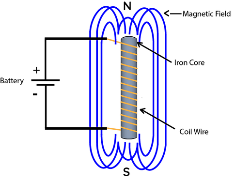
Illustration #6
Electromagnet
An electromagnet coil is a coil of wire that generates a magnetic field when an electric current passes through it. The core concept is that current flowing through a wire creates a magnetic field around it, a phenomenon described by Ampère’s law.
By winding the wire into a coil, the magnetic field becomes stronger and more concentrated, allowing for a controlled and powerful magnetic effect. By adjusting the current or the number of wire turns, the strength and properties of the magnetic field can be controlled for various applications.
Electromagnet Coils:
-
Coil Structure: An electromagnet coil typically consists of a wire wound into a tight spiral or helix. The number of turns (loops of wire) and the material of the wire are important factors in determining the strength of the magnetic field.
-
Electric Current: When an electric current (direct current, or DC) flows through the coil, it creates a magnetic field that is similar to that of a permanent magnet, but the field is temporary and can be turned on or off by controlling the current.
-
Magnetic Field: The magnetic field of an electromagnet coil is stronger when the wire is coiled more tightly or has more turns, and when a higher current is applied. The direction of the magnetic field can also be changed by reversing the current direction (using a DC power supply).
-
Core Material: Often, a ferromagnetic core (like iron) is placed inside the coil to concentrate and strengthen the magnetic field. This increases the efficiency of the electromagnet and makes the magnetic field more focused.
-
Applications:
-
Motors and Generators: Electromagnet coils are used in electric motors, generators, and transformers to create and manipulate magnetic fields.
-
Magnetic Lifting: They are used in cranes or other machines for lifting heavy metal objects.
-
Relays and Solenoids: Electromagnets are used in relays, solenoids, and switches to create motion or control circuits.
-
Properties of an Electromagnet Coil:
-
Strength of the Magnetic Field: The strength of the electromagnet's field is proportional to the current passing through the coil and the number of turns in the coil. The more turns and the higher the current, the stronger the magnetic field.
-
Temporary Magnet: Unlike permanent magnets, the magnetic field produced by an electromagnet is temporary and only exists when the current is flowing. When the current stops, the magnetic field disappears.
Example of Electromagnet Functional Circuit
Illustration #7
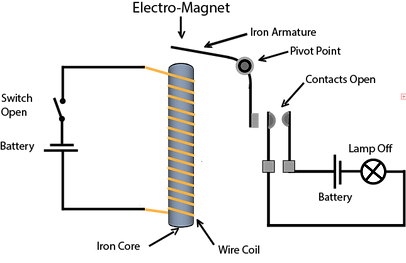

DC Generator
Permanent Magnet DC Generator
Illustration #8
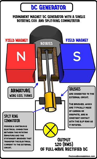

A DC generator is a device that converts mechanical energy into direct current (DC) electrical energy. The basic working principle of a DC generator is electromagnetic induction, which states that when a conductor (such as a coil of wire) moves through a magnetic field, an electric current is induced in the conductor.
Key Components of a DC Generator:
(Refer to illustration #8)
-
Armature: The rotating part of the generator, usually a coil or set of coils, that cuts the magnetic lines of force to induce current.
-
Field Magnet: A permanent magnet or electromagnet that provides the magnetic field in which the armature rotates.
-
Commutator: A split ring that reverses the direction of current in the armature windings to ensure the current always flows in the same direction (direct current). It acts as a mechanical rectifier.
-
Brushes: Carbon or graphite brushes that maintain electrical contact with the rotating commutator, allowing the current to be transferred to an external circuit.
Working Principle:
-
Mechanical Energy Input: The DC generator is driven by mechanical energy, which is typically supplied by a turbine, engine, or other rotating machinery.
-
Armature Rotation: The mechanical energy rotates the armature (a coil of wire) within the magnetic field produced by the field magnets.
-
Induced Current: As the armature rotates, the conductors (wires) in the armature cut through the magnetic lines of flux, inducing an electric current according to Faraday's Law of Electromagnetic Induction.
-
Commutator Function: The commutator ensures that the current flows in one direction (DC) by periodically reversing the connections of the armature windings to the external circuit. This eliminates the alternating current (AC) that would otherwise be generated as the armature moves.
-
Output of the Generator: The DC current flows through the brushes, commutator, and out to the external circuit.
Output of a DC Generator:
-
The output of a DC generator is direct current (DC). This means the current flows in only one direction, unlike alternating current (AC) which reverses direction periodically.
-
The output voltage and current depend on several factors:
-
The speed of rotation of the armature.
-
The strength of the magnetic field (which can be increased by using stronger magnets or increasing the current in the field windings).
-
The number of turns in the armature coil (more turns generate higher voltage).
-
The load connected to the generator.
-
Other Types of DC Generators:
-
Series DC Generator: The field windings are connected in series with the armature, which means the current flowing through the armature also flows through the field winding.
-
Shunt DC Generator: The field windings are connected in parallel with the armature, meaning the field winding gets a constant supply of voltage and is less affected by changes in load.
-
Compound DC Generator: This combines both series and shunt connections, providing a balance between the advantages of both types of generators.
AC Power Sources - Generators / Alternators
What is the Difference Between an AC Generator, and an Alternator?
An alternator is a device that converts mechanical energy into alternating current (AC) electrical energy. A generator is a broader term for a mechanical device that converts mechanical energy into either AC or direct current (DC) electrical energy. While an alternator always produces alternating current, a generator can generate either alternating or direct current depending on its design.
Understanding AC Power Sources: The Basics
In contrast to DC power, which flows in a constant direction, AC power is characterized by a flow of electric charge that alternates direction periodically. This alternating flow of current is what makes AC the preferred method of power transmission over long distances.
What is Alternating Current (AC)
Alternating current (AC) is a type of electrical current where the flow of electrons periodically reverses direction. AC current changes its direction back and forth in a regular pattern, typically in a sinusoidal wave, which we call a sine wave. (Illustration #9)
The AC generator from your local power company rotates 60 times a second. The sine waveform shown is the voltage produced in one complete cycle of the generator.
Illustration #9

-
Peak Voltage: The maximum value of voltage reached in either the positive or negative direction in a waveform.
-
Peak-to-Peak Voltage: The difference between the maximum positive and maximum negative voltage values in a waveform. It's the total voltage swing from the highest to the lowest point.
-
Average Voltage: The arithmetic mean of all instantaneous voltage values over one complete cycle. For a sine wave, this is approximately 0.637 times the peak voltage.
-
RMS (Root Mean Square) Voltage: The effective value of an AC voltage, equivalent to the DC voltage that would deliver the same power. For a sine wave, RMS voltage is approximately 0.707 times the peak voltage.
1. Why AC?
AC is preferred for electricity distribution over long distances because it is easier and more efficient to transform the voltage up or down using devices called transformers, which would be more difficult with DC.
2. How Does AC Power Work?
AC power works similarly to DC power in terms of the energy transfer in a circuit, but with a key difference: the current periodically changes direction.
-
Voltage in AC: In an AC circuit, the voltage also alternates between positive and negative values, creating a waveform. The peak voltage is the maximum voltage reached during each cycle, while the root mean square (RMS) voltage is a way of expressing the average voltage that delivers the same power as a DC voltage of that value.
For example:
-
If the peak voltage of an AC source is 169.7 V, the RMS voltage (which is the effective voltage for delivering power) will be about 120 V. This is why we often refer to household AC power in terms of 120 V or 240 V, which is the RMS voltage.
This alternating process produces the sinusoidal waveform.
Formula for AC Voltage (sinusoidal wave):
V(t) = Vpeak sin(2πft)
-
Where:
-
V(t) is the instantaneous voltage at time t.
-
Vpeak is the peak voltage,
-
f is the frequency (in Hz),
-
t is time.
-
This formula describes how the voltage varies sinusoidally with time.
3. Characteristics of AC Power
-
Frequency: The number of cycles the current completes per second, measured in hertz (Hz). In the U.S., household AC power is usually 60 Hz, and in many parts of Europe, it’s 50 Hz.
-
Peak Voltage and RMS Voltage: The peak voltage is the highest voltage achieved during each cycle of the AC wave.
-
For a 60 Hz AC supply, the peak voltage is approximately 170 V if the RMS voltage is 120 V (in the U.S.).
-
For a 50 Hz AC supply (commonly found in many countries like Europe), the RMS voltage might be 230 V, and the peak voltage will be around 325 V.
-
The RMS voltage is the effective voltage that would produce the same power as a DC voltage of that value.
4. AC Power in Circuits: How AC Works in Practice
When an AC power source (like a generator or the power grid) is connected to a circuit, it creates a changing voltage that causes current to flow through the circuit. This current flows through conductors, like wires, and powers devices like lights, motors, or appliances.
The current changes direction, moving back and forth in the conductor, which is why AC is ideal for things like motors. Inductive loads, like motors, which rely on the ability of AC to create a rotating magnetic field to induce motion, making them work efficiently.
-
Formula for AC Power in a Circuit: P = Vrms x Irms x cos(ϕ)
-
Where:
-
P is power in watts (W)
-
Vrms is the RMS voltage
-
Irms is the RMS current
-
cos(ϕ) is the power factor, which accounts for phase differences between voltage and current in certain circuits.
-
5. Transforming AC Voltage
-
One of the key advantages of AC power is that its voltage can easily be transformed using transformers. Transformers can step up or step down the voltage, which allows power to be transmitted efficiently over long distances and then converted to safer levels for use in homes or businesses.
-
Step-Up Transformer: Increases voltage to transmit electricity over long distances, where higher voltages minimize energy loss.
-
Step-Down Transformer: Reduces voltage to a usable level, such as 120 V or 230 V for household appliances.
6. Example of AC Power in Action: Powering a Household Lamp
-
When you plug a lamp into an AC power outlet, the AC voltage from the power grid, 120 V in the United States drives the current through the lamp's filament. Because the current is alternating, the filament experiences a periodic heating and cooling effect, but since the frequency of AC is high (60 Hz), the filament heats up and emits light continuously, appearing as steady illumination to the human eye.
7. AC vs. DC:
-
While DC power is used in smaller applications like batteries, AC power is preferred for transmission over long distances due to the ease of stepping up and stepping down voltages using transformers. AC power can also be generated more efficiently, and devices like electric motors work well with AC because of the way the current alternates direction to create rotating magnetic fields.
AC Generator
Single Coil / Phase AC Generator with Permanant Magnet Stator
Illustration #10
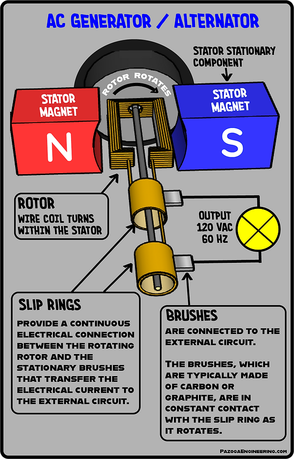
Single-Coil AC Generator with Permanent Magnet Stator
(Illustration #10)
An AC generator (alternator) is a device that converts mechanical energy into alternating current (AC) electrical energy. The principle behind its operation is electromagnetic induction — when a conductor moves through a magnetic field, a current is induced in the conductor. In this configuration, the magnetic field is stationary, and the coil rotates.
Key Components of a Simple AC Generator:
(Illustration # 10)
-
Stator (Permanent Magnets):
Two fixed magnets (North and South poles) mounted on opposite sides of the stator frame. These magnets create a constant magnetic field through which the rotor coil spins. -
Rotor (Armature Coil):
A single coil of wire mounted on a shaft that spins within the magnetic field. This rotating coil is where the electrical current is generated. -
Slip Rings:
Two continuous (unsegmented) metal rings connected to the ends of the rotating coil. As the rotor spins, the slip rings rotate with it and allow the induced current to be transferred to an external circuit without changing the coil's internal current direction. -
Brushes:
Stationary carbon or graphite contacts that press against the rotating slip rings, providing a path for the alternating current to flow out to an external circuit.
Working Principle:
-
Mechanical Energy Input:
Mechanical energy from a turbine, crank, engine, or motor is used to spin the rotor coil inside the generator. -
Coil Rotation in Magnetic Field:
As the rotor coil spins between the North and South poles of the stator magnets, it cuts through the magnetic field lines. -
Induced Alternating Current:
According to Faraday’s Law of Electromagnetic Induction, this motion induces a current in the coil. As the coil rotates, the direction of the magnetic flux through it changes continuously, which causes the induced current to reverse direction periodically, producing alternating current (AC). -
Slip Rings and Brushes:
The ends of the rotating coil are connected to slip rings, which rotate along with the rotor. The brushes maintain contact with the slip rings, allowing the alternating current to flow to the external load.
AC Generator Output:
The output of this type of generator is alternating current, characterized by a sinusoidal waveform. The current reverses direction once every half-rotation of the coil. The frequency of the AC (e.g., 60 Hz or 50 Hz) depends on:
-
The rotational speed of the coil (RPM).
-
The number of magnetic pole pairs in the stator.